Review Article
Use of Geosynthetic materials in solid waste landfill design: A review of geosynthetic related stability issues

Lin Zhao1 and MA Karim2*
1Graduate Student, Department of Civil and Construction Engineering, Kennesaw State Universality Marietta Campus, 1100 South Marietta Parkway, Marietta, 30060, Georgia2Associate Professor and Assistant Department Chair, Department of Civil and Construction Engineering, Kennesaw State Universality Marietta Campus, 1100 South Marietta Parkway, Marietta, 30060, Georgia
*Address for Correspondence: MA Karim, Associate Professor and Assistant Department Chair, Department of Civil and Construction Engineering, Kennesaw State Universality Marietta Campus, 1100 South Marietta Parkway, Marietta, Georgia 30060, Tel: 470-578-5078; Email: [email protected]; [email protected]
Dates: Submitted: 11 June 2018; Approved: 21 June 2018; Published: 22 June 2018
How to cite this article: Zhao L, Karim MA. Use of Geosynthetic materials in solid waste landfill design: A review of geosynthetic related stability issues. Ann Civil Environ Eng. 2018; 2: 006-015. DOI: 10.29328/journal.acee.1001010
Copyright License: © 2018 Zhao L, et al. This is an open access article distributed under the Creative Commons Attribution License, which permits unrestricted use, distribution, and reproduction in any medium, provided the original work is properly cited.
Keywords: Geosynthetics; Solid waste landfill; Slope failure; Slope stability; Shear strength; Triggering cause
Abstract
Geosynthetics used in landfills provides a technical and economic advantages over traditional clay liners. It may create stability issue and even lead to landfill failure due to its low interface or internal shear strength if improperly designed and/or constructed. The most common failure mechanism in geosynthetic-lined landfills is transitional failure involving waste and bottom liner (deep-seated failure) or only final cover system (shallow failure). Shear strengths of geosynthetic-geosynthetic and geosynthetic-soil have a wide range of variations. Shear strengths of interface from literature may be used in preliminary design. For final design, site-specific interface shear strengths shall be used. Internal shear strengths of unreinforced geosynthetic clay liner (GCL) are less than those of reinforced GCLs. Unreinforced GCLs are not recommended for slopes steeper than 1:10 (1 Vertical and 10 Horizontal). Peak shear strength of interface and internal GCLs can be used in bottom liner; residual shear strength of interface and internal GCLs shall be used for geosynthetic placed along the slopes. Site-specific shear strengths of waste are recommended to be used in the design. Landfill failure could be triggered by static loadings including excessive leachate, pore pressure above the bottom liners, gas pressure, and excessive wetness of the geomembrane-GCL, and earthquake loading. The factor of safety of 1.5 is recommended for static loading and 1.0 for earthquake loading. A higher factor of safety is recommended if a failure could have a catastrophic effect on human health or the environment, and if large uncertainty exists in input parameters to calculate the factors of safety. The main objective of this review article is to provide a comprehensive knowledge of slope failure mechanisms, causes, and probable remedies in one place.
Introduction
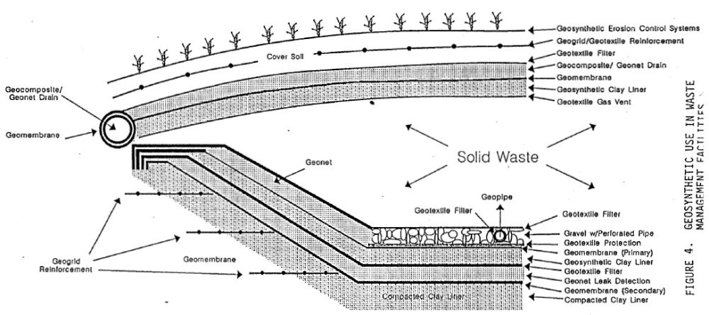
Geosynthetics are most commonly used in solid waste landfills to protect surface water and groundwater due to their multiple functions, excellent hydraulic properties, ease of installation, and cost saving [1]. Geosynthetic used in landfill include non-woven geotextile, woven geotextile, geogrid, geomembrane, geocells, geosynthetic clay liner (GCL), geonet, geocomposite, etc, and each geosynthetic type serves as specific functions. The functions that geosynthetic system can serve in landfill are separation, drainage, filtration, hydraulic barrier, gas barrier, and protection [1]. Table 1 summarizes geosynthetic types and their functions, and Figure 1 illustrates their use in landfills. Geomembrane, GCL, geopipe, and geotextile are more commonly used geosynthetic materials in landfill applications while geonet, geocomposite, and geogrid are used a lesser extent [1].
| Table 1: Functions of Geosynteteic Materials in Solid Waste Landfill Design [1] | ||
| Function | Description | Geosynthetic Type |
| Separation | placed between two different materials to maintain or improve the integrity and functioning of both materials | Non-woven geotextile; woven geotextile; geocells; geocomposite |
| Reinforcement | provides tensile strength in materials that lacks sufficient tensile capacity | Woven geotextile; geogrids; geocells; geocomposite |
| Filtration | allows water or gas flow across it while retaining the fine particles on its upstream side | Non-woven geotextile; woven geotextile; geocomposite |
| Drainage | transmits flow within the plane of their structure | Non-woven geotextile; geopipe; geocomposite; geonet |
| Hydraulic/Gas Barrier | relatively impervious material to contain liquids or gasses | Non-woven geotextile; geomembrane; geosynthetic clay liner; geocomposite; geonet |
| Protection | provides a cushion above/below to prevent damage by punctures during placement of overlying materials. | Non-woven geotextile; geosynthetic clay liner; geocomposite |
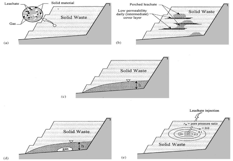
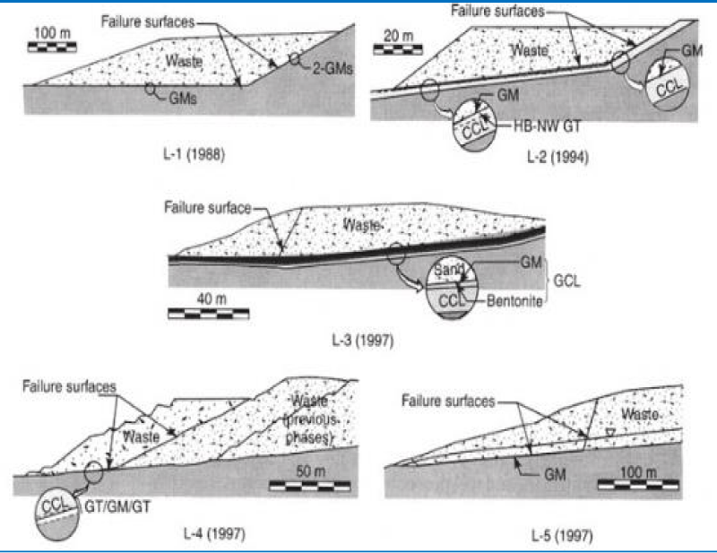
While geosynthetic system provides huge economic and technical advantage over traditional liners, it may create stability issue and even lead to landfill failure if improperly designed and/or constructed. One of the most important problems associated with the use of geosynthetics for landfill linings is their stability. This becomes a very important issue by the fact that more and more landfills are designed and constructed with a small footprint and require moderate to steep slopes to raise their capacity [3]. There have been massive failures of landfills related to geosynthetic systems. For example, Koerner and Soong [4] reported five failed landfill sites that contained geomembrane liners with volumes from 60,000 to 1,200,000 m3. These landfill failures caused dramatic damage to the environment, and resulted in litigations and fines. The five failure scenarios are presenmted in figure 2. In this respect, evaluation of geosynthetic related stability is a critical consideration for landfill design, construction, and operation. As such, this review paper is concerned on failure mechanisms, shear strengths, triggering factors of geosynthetic-lined landfill failures and design criteria.
Figure 2: Various leachate distribution scenarios in landfills. (a) Discontinuous leachate, (b) perched or localized leachate, (c) leachate head on liner, (d) leachate head above gas on liner, and (e) leachate under excess pore pressure [4].
Landfill slope failure mechanisms
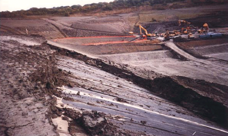
Landfill slope failure can be classified as two major types: rotational failure and translational failure. Translational failures are more prevalent in landfills containing geosynthetics while rotational failure is more common in landfills without geosynthetics. This is because geosynthetic-geosynthetic interface, internal GCLs, geosynthetic-waste interface and geosynthetic-soil interface are weaker in shear strengths than waste materials and foundation soils, and thus represent weaker planar failure surfaces in landfills, at which landfill slide can occur [5]. The landfills without geosynthetics contain relatively uniform materials without a weaker prevalent planar surface. Translational failures tend to occur when dissimilar materials are involved while rotational failures tend to occur through a relatively uniform material [5]. Figure 3 presents translational failure along the interface of geomembrane-geotextile interface, geotextile-geomembrane interface, GCLs, and geomembrane-waste.
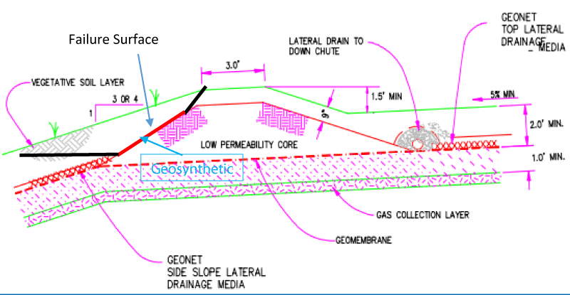
Translational failure in landfills containing geosynthetics can be further classified as deep-seated translational failure and shallow translational failure. Deep-seated translational failure occurs along the geosynthetics placed as bottom liner or along internal slope. Shallow translational failure occurs along the geosynthetics placed in the final cover system. All failures in figure 3 are deep-seated failure. Figures 4,5 show shallow translational slope failures in the final cover system. Deep-seated translational failure involves the movement of waste while shallow translational failure typically involves the movement of the cover system and can be repaired with less effort than deep-seated translational failure. Additionally, deep-seated translational failure poses more damage to the environment and incurs significant cost to repair.
Case Histories
Richardson et al. [9], reported a shallow translational slide occurred during construction of one-six-hare final cover project. The slope on which the slide occurred is inclined at 14 degrees with an 1V:4H (1 Vertical and 4 Horizontal), and the slope is 60 feet high with no benches. The cover system consisted of topsoil, vegetative soil, drainage sand, polyvinyl chloride (PVC), geomembrane, GCL, and gas relief system from top to bottom. Failure of the cover system took place when the drainage sand layer. The sand above the geomembrane and the geomembrane moved downslope along the geomembrane/GCL interface [9]. The cover system failure was induced by a combination of low interface shear strength of geomembrane-GCL interface, excess pore pressure, and gas pressure below the GCLs [9].
The Kettleman Hill Landfill failure is one of the most famous deep-seated translational slide landfill failures, which has been extensively studied by various authors [3]. The Kettleman Hills Unit B-19, Phase 1-A landfill had an area of about 120,000 m2 and was part of a waste treatment and storage facility at Kettleman Hills, California. The landfill has straight-sided liner with an oval-shaped bowl, which had a nearly level base. The solid waste placement and soil cover construction began in 1987 and progressed at an essentially steady rate. The landfill slid on March 19, 1988, resulting in a lateral movement of the fill of 35 feet towards the southeast. The vertical displacement was up to 14 feet along the back of the sliding mass. Surface cracking and tears and displacement of the geosynthetic liner were clearly visible. The sliding mass slid along the liner system. There were no rain, earthquakes, or other triggering events during the failure. Many studies believe that the failure occurred because the waste fill placed on the top of landfill reached a height that created a marginal stability of landfill slope. Major reasons that could contributed this landfill failure include that (1) the friction angle could be as low as 8 degrees between layers of geosynthetic materials; the interface between geomembranes and compacted clay could have only a few hundred pound per square foot; (2) the over-wetness yielded a very ow shearing strength at geomembrane/clay interfaces; and (3) the conditions at which the liner interface strengths were tested were different from the field conditions, and the interface shear strengths could not represent the site-specific shear strength [3].
Shear strengths of interface and waste and internal shear strength of GCL
Slope failure in geosynthetic lined landfills, as discussed in the previous sections, could occur along the following weak planes:
1. Soil-Geosynthetics Interface;
2. Geosynthetic-Geosynthetic Interface; and
3. Geosynthetic-Waste Interface.
4. Bentonite within GCL
5. Waste
Interface shear strengths
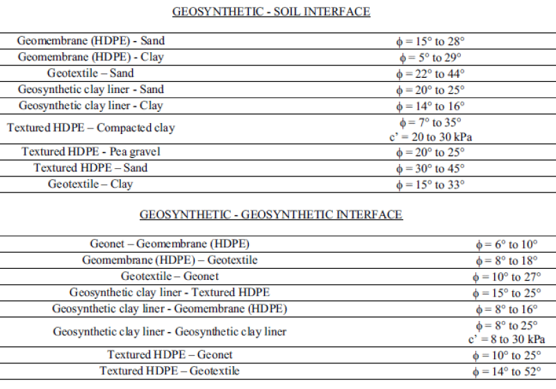
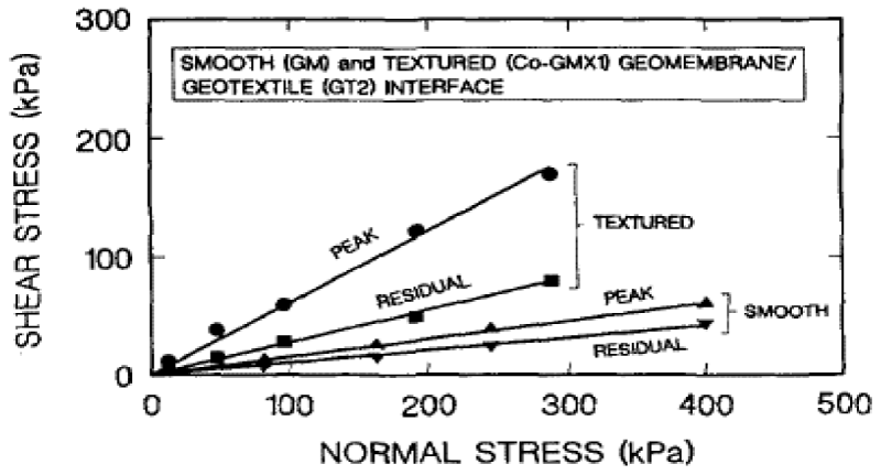
Bouazza et al. [1], summarized the ranges of interface strengths between geosynthetics collected from the literature (Table 2). Table 2 shows a very wide range of variations in interface shear strengths, which is due to different types of the geosynthetics materials, different testing conditions, testing protocols and testing equipment [1]. As such, interface shear strength from the published values are not recommended to be used in the landfill design; however, they can be used in a preliminary design. The site-specific testing shall be performed to obtain interface shear strength on a site-specific basis for design. Figure 6 presents comparison of failure envelope for smooth and textured geomembrane-geotextile interfaces, and peak shear strength and residual strength. Textured geomembrane/geotextile has greater friction angle than smooth geomembrane-geotextile. If a higher shear resistance is desired for the design, textured geomembrane can be used to replace the smooth geomembrane.
Figure 6: Comparison of Failure Envelope for Smooth and Textured Geomembrane/Geotextile Interfaces [11].
One major issue with geosynthetics placed in slopes is their strain softening behavior when subjected to shear forces [1]. When sheared, the peak interface shear strength is mobilized within few millimeters, and then its shear strength decreases to a residual strength, which is significantly less than the peak shear strength. This raises one question for design engineers: if the peak shear strength or residual shear strength shall be used for the interface and internal geosynthetic materials during the landfill design. Jones and Dixon [9] and Gilbert [12] stressed the importance of residual strength resistance and its implication on design. Gilbert [12] proposed that both peak and residual strengths are used for landfill design. The peak shear strength can be used to find slippage location, while the residual strengths can be used to evaluate the stability of geosynthetic lined landfill. It is common practice to use the peak shear strength for the interface at the floor and the residual shear strength value shall be used for the geosynthetic placed on side slope [5].
Internal shear strength of GCL
When GCLs are used in a landfill, one slope stability concern is mid-plane shear through the bentonite layer. Peak shear strengths for the unreinforced GCL products are similar to those for sodium bentonite, which has very low shear strength, and makes them prone to sliding. Furthermore, shear strength of hydrated bentonite could have a friction angle as low as 6 degrees [13]. Because of this low friction angle, unreinforced GCLs are usually not recommended for slopes steeper than 1V:10H [14].
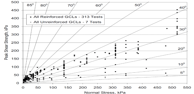
To increase the internal shear strength of GCLs, GCL manufacturers have created “reinforced” GCLs in which the two outer layers of geotextile are either needle-punched or stitched together through the bentonite layer [13]. Reinforced GCLs have greater internal peak strength due to the presence of fiber reinforcements. The peak shear strength of different types of reinforced GCLs (needle-punched, thermal bonded, stitch-bonded) may differ significantly [15].
Figure 7 shows the results of the internal shear strengths of both reinforced and unreinforced GCLs [15]. The frictional angles of reinforced GCLs have a wide range from 10 to 45 degrees, while unreinforced GCLs have frictional angles typically less than 15 degrees.
Shear strengths of waste
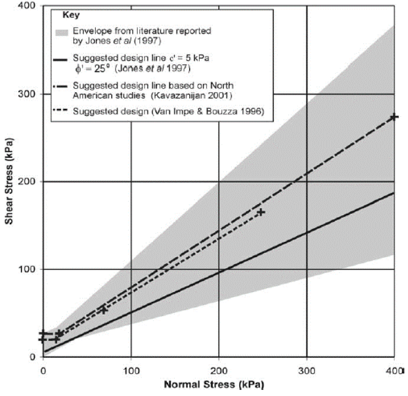
The measured shear strengths obtained from the literature have a wide range. The reported friction angles range from 15 degrees to 42 degrees with cohesion ranging 0 to 28 kPa [8]. This large scatter is due to the large variety and heterogeneous of wastes, which results in the difficulties to obtain representative shear strength. Jones and Dixon [8] suggested municipal solid waste (MSW) shear strength envelopes for design as shown in figure 8.
Due to large variation of shear strengths, site-specific data is recommended to be used in the design of landfill. However, if no site specific is available the approach proposed by Van Impe and Bouazza [16] can be used as a starting point in design. This approach defines design values of cohesion (c) and friction (φ) into three distinct zones:
• “Zone A: corresponding to very low stress (0 kPa ≤ σv < 20 kPa) where the MSW behavior can be described as being only cohesive. In this case, c = 20 kPa.”
• “Zone B: corresponding to low to moderate stresses (20 kPa ≤ σv < 60 kPa). In this case, c = 0 kPa and φ ≈ 38°.”
• “Zone C: corresponding to higher stresses (σv ≥ 60 kPa). In this case, c ≥ 20 kPa and φ ≈ 30°.”
Triggering mechanism
Landfill failures are often induced by processes that either increase the driving force or decrease the resistant force along the weak plane, typically an interface between two geosynthetics, or an interface between a geosynthetic or both [5]. Major contributing causes of landfill failures include the following:
1. Rise in leachate level within the waste mass that exceeds the maximum allowable level;
2. Excessive buildup of leachate level due to liquid waste/leachate injection that exceeds the maximum allowable level;
3. Excessive pore pressure buildup in the final cover system that exceeds the maximum allowable level;
4. Excessive gas buildup below final cover system;
5. Excessive wetness of the Geomembrane-GCL interface resulting in a lower shear strength; and
6. Earthquake or blasting.
The above causes can be grouped into two loading cases: static loading (Cause No. 1 thru 5) and seismic loading (Cause No. 6).
Stability design criteria
According to Ohio EPA [5], the following factors of safety (FS) should be used to evaluate landfill stability:
1. Static analysis: FS > 1.50
2. Seismic analysis: FS > 1.00
The use of higher factors of safety is recommended if a failure could create catastrophic effect on the environment and human health, and if large uncertainty exists in input parameters to calculate the factors of safety [5].
Conclusions and Recommendations
A number of technical papers related to stability of geosynthetic-lined landfill have been reviewed, and the following conclusions and recommendations were made:
1. Geosynthetics used in landfills provides an economic and technical advantages over traditional liners. But it may create stability issue and even lead to landfill failure due to its low interface or internal shear strength if improperly designed and/or constructed.
2. The most common failure mechanism in geosynthetic-lined landfills is transitional failure involving waste and bottom liner (deep-seated failure) or only final cover system (shallow failure).
3. Shear strengths of geosynthetic-geosynthetic and geosynthetic-soil have a wide range of variations. Shear strengths of interface from literature may be used in preliminary design. For final design, site-specific interface shear strengths shall be used.
4. Internal shear strength of unreinforced GCLs are less than those of reinforced GCLs. unreinforced GCLs are usually not recommended for slopes steeper than 1V:10H.
5. Peak shear strength of interface and internal GCLs can be used in bottom liner; residual shear strength of interface and internal GCLs shall be used for geosynthetic placed along the slopes.
6. The measured shear strengths of waste obtained from the literature have a wide range with reported friction angles ranging from 15 degrees to 42 degrees and cohesion ranging 0 to 28 kPa. Due to large variation of shear strengths, site-specific data is recommended to be used in the design of landfill. If no site specific is available the approach proposed by Van Impe and Bouazza [16] can be used as a starting point.
7. Landfill failure could be triggered by static loadings including excessive leachate, excessive pore pressure above the bottom liners and excessive gas pressure and excessive wetness of the geomembrane-GCL, and earthquake and blasting loading.
8. The factor of safety of 1.5 is recommended for static loading and 1.0 for earthquake loading. A higher factor of safety is recommended if a failure could create a catastrophic effect on the environment or human health, or if large uncertainty exists in input parameters to calculate the factors of safety.
References
- Bouazza A, Zornberg JG, Adam D. Geosynthetics in Waste Containment Facilities: Recent Advances. Geosynthetics. 2002; 2: 445-510. Ref.: https://tinyurl.com/y78rg6f4
- Landreth RE. Opportunity for Use of Geosynthetics in Waste Management Facilities. 2nd International High-Performance Fabrics Conference Proceedings. 1992; 153-166. Ref.: https://tinyurl.com/y7mx28rh
- Mitchell JK, Chang M, Seed RB. The Kettleman Hills Landfill Failure: A Retrospective View of the Failure Investigations. International Conference on Case Histories in Geotechnical Engineering. 1993. Ref.: https://tinyurl.com/y6vpqo6t
- Koerner RM, Soong TY. Leachate in landfills: the stability issues. Geotextile and Geomembrane. 2000; 18: 293-309. Ref.: https://tinyurl.com/yag7g2dj
- Ohio EPA. Geotechnical and Stability Analyses for Ohio Waste Containment Facilities. 2004. Ref.: https://tinyurl.com/ya3sebe3
- Robert M Koerner. Design with Geosynthetics. 6th Edition. 2012.
- Richardson GN, Zhao A. Geosynthetic Fundamentals in Landfill Design. Advances in Environmental Geotechnics. 2009. Ref.: https://tinyurl.com/y9uvxwxd
- Jones DRV, Dixon N. Stability of Landfill Lining Systems: Report No. 1 Literature Review. R&D Technical Report. 2003. Ref.: https://tinyurl.com/y7yzwzdq
- Jones DRV, Dixon N. A comparison of geomembrane/geotextile interface shear strength by direct shear and ring shear. Proceedings 2nd European Conference on Geosynthetics. 2000; 2: 929-932.
- Richardson GN, Thiel RS, Marr WA. Lessons Learned From the Failure of a GCL/Geomembrane Barrier on a Side Slope Landfill Cover. 2000.
- Stark TD, Williamson TA, Eid HT. HDPE Geomembrane/Geotextiles Interface Shear Strength. J Geotechnical Engineering. 1996; 122. Ref.: https://tinyurl.com/y8pjw9sq
- Gilbert RB. Peak versus residual strength for waste containment systems. Proceedings 15th GRI Conference. 2001; 29-39.
- Thiel Engineering. Engineering Report: Appendix C Volume 2 - Alternative Bottom Liner System, Cowlitz County Headquarters Landfill Project, Cowlitz County, Washington. 2009.
- Richardson GN. GCL internal shear strength requirements. Geosynthetics Fabric Report. 1997; 15: 20-25. Ref.: https://tinyurl.com/y7uzd7bt
- McCartney JS, Zornberg JG, Swan R. Internal and Interface Shear Strength of Geosynthetic Clay Liners (GCLs). Geotechnical Research Report. 2002; 386. Ref.: https://tinyurl.com/y9qaeu2o
- Van Impe WF, Bouazza A. Geotechnical Properties of MSW. 2nd Int. Congress on Environmental Geotechnics. The Netherlands.

